

Deligreencs
EU Stock -JK V19 51.2V 280AH 314AH Battery Pack Floor-standing DIY Kits
EU Stock -JK V19 51.2V 280AH 314AH Battery Pack Floor-standing DIY Kits
Impossible de charger la disponibilité du service de retrait
Free Shipping | No tax | Door to Door
Standard Kit Contents:
1. Battery Case
2. PCB Board
3. BMS
4. Display Screen
5. Busbars
6. Positive & Negative Terminals
7. Cables & Wiring Harness
8. Epoxy Insulation Boards
9. Insulation Pads
10. Screws, Nuts & Mounting Hardware
11. Caster Wheels
12. Mounting Brackets

| Parameter | Specification |
|---|---|
| Rated Energy (kWh) | 16kWh |
| Configuration | IP 16S |
| Nominal Voltage (V) | 51.2 V |
| Working Voltage Range (V) | 42 V ~ 58.4 V |
| Nominal Capacity (Ah) | 300 Ah |
| Rated Charge/Discharge Current (A) | 100 A (Charge) / 200 A (Discharge) @ 25±2°C |
| Maximum Continuous Charge Current (A) | 200 A @ 25±2°C |
| Maximum Continuous Discharge Current (A) | 200 A @ 25±2°C |
| Operating Temperature (°C) |
Charge: 0 ~ 40°C Discharge: -20 ~ 60°C |
| Humidity Range (%) | 5% ~ 95% |
| Altitude Limit (m) | 0 ~ 3000 m |
| Weight (kg) | 32kg |
| Dimensions (mm) | 797 × 415 × 270 mm |
| Storage Temperature/Humidity |
Within 1 month: -10°C ~ 35°C Within 3 months: 25±2°C, 65%±20% RH |
| Cycle Life | 8000 cycles @ 25°C, 50A charge/discharge current, 80% DOD |
| IP Rating | IP20 |
| Communication Interface | CAN & RS485 |

Safety architecture
Three layers, each rated deliberately relative to the next.
Layer 1 — BMS protections. Per-cell over- and under-voltage, charge and discharge overcurrent, charge and discharge over-temperature, charge low-temperature, MOSFET over-temperature, and short circuit with a 5 µs detection window. All thresholds are user-settable in the app.

Layer 2 — the 250 A DC breaker. Sits above the 200 A continuous rating so it never nuisance-trips during normal operation, and below the BMS's 400 A instantaneous ceiling so it interrupts before the board is asked to survive a fault it was not built for. It is also your maintenance isolator: open it before touching anything inside the box.

Layer 3 — mechanical. The A/B PCB busbar boards fix the series path geometry so a busbar cannot bridge the wrong pair of terminals during assembly, and hold the sense leads at a defined pitch. Epoxy boards isolate the cell block from the enclosure wall; EVA pads maintain compression between cells across the pack's life.

One thing no product can do for you: torque. M6 terminal bolts, [CONFIRM: your figure, typically 7.5 N·m]. Under-torque gives a high-resistance joint that heats under load. Over-torque strips an aluminium terminal and writes off the cell. At 200A a bad joint is not a reliability problem, it is a fire.
Four numbers worth understanding
0.35 mΩ internal loop resistance. This is the resistance of the BMS's own current path, and it is the lowest in the PB series — the 150A board is 0.45 mΩ, the 100A board is 1 mΩ. At a full 200A, this board dissipates about 14 W internally. A board with 1 mΩ would dissipate 40 W at the same current and run hot enough to start throttling. If you are planning to actually pull 200A rather than just own a 200A label, this difference matters.
±3 mV acquisition accuracy. Balancing decisions are only as good as the measurement behind them. The factory balance trigger is a 10 mV delta; with ±3 mV measurement error you are resolving real imbalance, not chasing noise. Cheaper boards with ±20 mV accuracy cannot meaningfully balance at that threshold.
2A active balance. Charge is pulled out of the strong cell and delivered into the weak one, so every amp-hour moved counts twice — one cell falls while the other rises. At roughly twenty times the current a passive balancer can manage, and running during charge, discharge and rest rather than only at the top of charge, divergence is corrected in hours rather than days.
The limit no balancer escapes. Balancing corrects state-of-charge divergence. It cannot correct capacity mismatch. If one cell genuinely holds 3% less than its neighbours, it will re-diverge on every single cycle no matter how much balance current you throw at it, and it will clip your usable window from both ends. That is a cell-selection problem, not a BMS problem — which is why buying matched cells from one batch, and top-balancing properly before assembly, matter more to pack life than any number on a BMS .
1100 mW operating draw. About 26 Wh per day, roughly 0.18% of a 14.3 kWh pack. Intelligent sleep drops this to 12 mW when charge and discharge current stay below 1 A for 26 consecutive hours.
Communication and pinouts
Published so you can build or verify a cable before the box arrives. Source: specification section 5.2.
RS485-1 (RJ45) — inverter communication
| Pin | Signal |
|---|---|
| 1, 8 | RS485-B1 |
| 2, 7 | RS485-A1 |
| 3, 6 | GND |
| 4, 5 | NC |
CAN (RJ45) — inverter communication, 250 kbps default
| Pin | Signal |
|---|---|
| 4 | CANL |
| 5 | CANH |
| 7 | GND |
| 1, 2, 3, 6, 8 | NC |
RS485-2 (RJ45 ×2) — pack-to-pack parallel bus and PC monitoring, 115200 baud
| Pin | Signal |
|---|---|
| 1, 8 | RS485-B2 |
| 2, 7 | RS485-A2 |
| 3, 6 | GND |
| 4, 5 | NC |
Dry contacts (2 channels): COM1 / S1, COM2 / S2. Drive an external buzzer or a cooling fan on over-temperature, overcharge or over-discharge.
Inverter protocol profiles are selected in the JK app or on the LCD — no firmware flashing. Profiles exist for Deye, Growatt, GoodWe, SMA, Solis, Victron and other major hybrid inverter families.
What we will not claim. A protocol profile existing is not the same as your specific unit working. Compatibility depends on your inverter's model, firmware revision and the cable pinout — CAN and RS485 both use RJ45 housings and are not interchangeable. Send us your exact model and firmware version. We will give you the protocol setting and the pinout, or tell you plainly that we have not tested it.
Assembly and commissioning
- Inspect and photograph the kit before assembly. It simplifies any warranty claim.
- Measure each cell's open-circuit voltage and internal resistance. Record them.
- Top-balance all 16 cells to within 10 mV. This is the highest-value hour of the build. The BMS balances a healthy pack; it does not rescue a badly divergent one.
- Fit epoxy isolation boards and EVA pads. Load cells observing polarity.
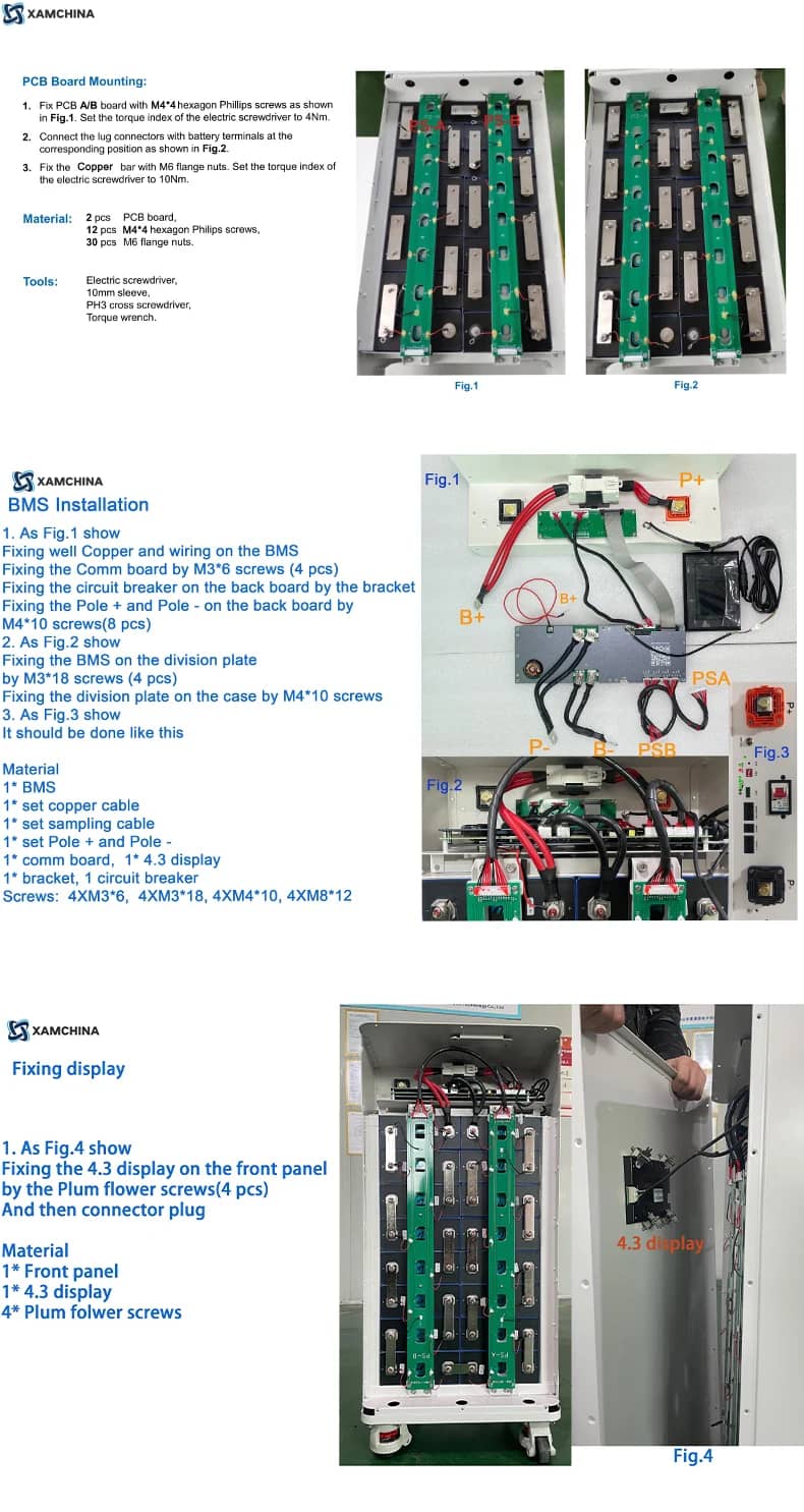
- Install the A/B busbar boards. Torque to specification in a diagonal pattern.
- Connect the sense harness last. Verify the voltage at each connector pin against the cell before seating it. The V19 revision uses colour-coded connectors, which makes a reversed insert much harder, but it does not make it impossible.
- Confirm P− and B− are correctly connected and the board is mechanically secured before applying any power. Jikong's own manual warns that getting this wrong can destroy the board.
- Mount the display and breaker. Keep power cables physically separated from signal cables.
- Power up, verify all 16 cell voltages on the display, then apply the settings from the table above.
- Close the breaker and commission against your inverter.
Illustrated manual and step-by-step build video are sent with your order confirmation, and available before purchase on request.
Factory defaults vs. what we recommend
Please click the link below for details. 👉JK BMS Recommended Settings
Known gotchas — read before you email us
"The BMS is dead out of the box." It almost certainly is not. The board has no power switch. It ships in an unactivated state and is designed for charge activation: connect a charger at roughly 2 V above pack voltage and it wakes. It also wakes from the display button, or the button on the interface board. This is the single most common false alarm we see.
"It tripped short-circuit protection the first time I connected the inverter." Normal, and covered in the manual. Inverters have large input capacitors; the inrush on first connection can exceed the short-circuit threshold. Increase the short-circuit protection delay from the 5 µs default, after you have confirmed there is genuinely no short in the external wiring.
"It went to sleep and I can't find it." Intelligent sleep activates after 26 consecutive hours below 1 A in both directions. Wake it with the button or a charger. You can disable sleep in the app's BMS control page.
"Charging is stuck at about 10 A." That is the charge current-limiting function doing its job after a charge overcurrent event. Check why the overcurrent occurred rather than disabling the feature.
"My cell voltages read fine but one channel shows zero." Check pin 3 of connector P8 — it is a reserved pin, not a cell tap. Count your harness positions against the manual before assuming a fault.
Scaling to a bigger bank
Up to 16 packs in parallel on the RS485-2 bus — roughly 229 kWh at 314Ah per pack.
Each BMS gets a unique address, 0 to 15, set on the 4-position DIP switch. Address 0 is the master; 1 through 15 are slaves. Packs are daisy-chained RJ45 to RJ45 on RS485-2; a USB-to-RS485 cable from the master reaches the Jikong PC monitoring software, which polls all packs on one screen. The master's L6 LED blinks; slave L6 LEDs blink once they have successfully linked to the master.
Before you parallel anything:
- Check your inverter's supported pack count. Many hybrid inverters cap at 6, 10 or 16 regardless of what the BMS allows, and that number is usually the real limit.
- Bring all packs to within 0.5 V of each other before the first parallel connection, or inrush between packs will trip breakers.
- Use equal-length cables from each pack to the busbar so current shares evenly.
- Set the DIP addresses before powering up, not after.
Shipping, taxes, warranty
Stocked in Poland. Shipped DDP — duties and import VAT prepaid, nothing collected at your door. 5–10 working days across the EU, tracking issued at dispatch.
Warranty: [ 5-year]
FAQ
Are cells included? No. This is the enclosure and electronics kit. You supply 16 prismatic cells. We stock matched Grade A cells in the same EU warehouse and can ship them together.
Is this a genuine Jikong board? Yes — JK-PB2A16S-20P, hardware revision V19, as covered by Jikong specification V19.0.1. Every BMS figure on this page is traceable to that document, which you can download above.
How much energy will the finished pack hold? 16 cells in series, 51.2 V nominal: 14.3 kWh at 280Ah, 16.1 kWh at 314Ah, 16.4 kWh at 320Ah.
Can I use cells I already own? If they are the standard 71–72 × 174 × 207 mm prismatic format and 280–320Ah, very likely. Send us a photo of the cell label and terminal face and we will confirm before you order.
Will it talk to my inverter? Protocol profiles exist for Deye, Growatt, GoodWe, SMA, Solis, Victron and others. Whether your specific model and firmware work depends on the cable pinout as much as the protocol. Send us the model number.
Why 200A rather than 150A? At 51.2 V, 200 A is about 10.2 kW continuous; a 150 A board caps near 7.6 kW. The 200 A board also has lower internal resistance — 0.35 mΩ against 0.45 mΩ — so it runs cooler at any given current, not only at the top end.
What is the difference between active and passive balancing? Passive balancing burns excess charge from strong cells as heat, typically at 50–100 mA and only during charge. Active balancing transfers charge from strong cells into weak ones at 2 A, during charge, discharge and rest. On 280Ah-plus cells, passive balancing cannot keep pace with real divergence.
Do I need the heating function? Only if the pack will sit below 0 °C. The board has a 10 A heating output as standard. Jikong recommends wiring a normally-closed 45–65 °C thermostat in series with the heater as a second layer of protection. [CONFIRM: whether a heating pad is included in your kit.]
How many packs can I run in parallel? Sixteen, addresses 0 to 15 on the DIP switch. Your inverter's supported pack count is usually the binding constraint.
Is it certified for grid-tied installation? See the section above — we answer that one directly rather than burying it.
In stock in Poland. Dispatched within 24 hours. Add to cart — or send us your cell model and inverter model on WhatsApp and get a written compatibility check first. We would rather answer five questions than process one return.